Pioneer PD-F1007 User Manual Page 10
- Page / 84
- Table of contents
- TROUBLESHOOTING
- BOOKMARKS
- Operating Instructions 1
- Mode d'emploi 1
- Bedienungsanleitung 1
- Istruzioni per l'uso 1
- LASER PRODUCT 2
- IMPORTANT 3
- BEFORE YOU USE THE PLAYER 4
- ^ f^iOnGGr 5
- CAUTIONS REGARDING HANDLING 6
- PRECAUTIONS DIVERSES 7
- CONNECTIONS 8
- RACCORDEMENTS 8
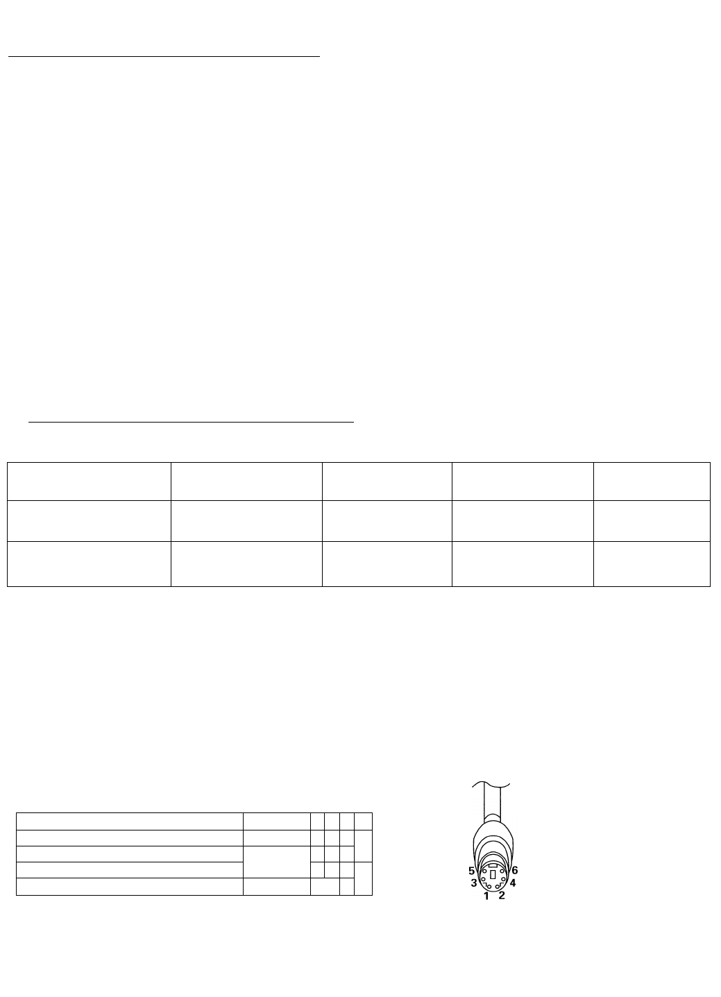
- ® Connecting another PD-F1007 9
- Frprr r iM' i°iMi li i 10
- --LL Pr hri rr i 1 10
- I" I_____________Lü 11
- @ OPEN/CLOSE button (14, 18) 12
- (il) (16) 13
- (II) button (16) 13
- HOW TO LOAD THE DISCS 14
- CHARGEMENT DES DISQUES 14
- To remove the discs 15
- Pour retirer les disques 15
- BASIC OPERATIONS 16
- OPERATIONS DE BASE 16
- J 17
- <PRD1052> 20
- VARIOUS OPERATIONS 21
- FONCTIONS DIVERSES 21
- I O _n l_ n I ■ n 3 22
- I _l U I U r U _i 22
- (Lecture programmée) 24
- ^ I ' J' 27
- To use the TIME/CHARA button 29
- TROUBLESHOOTING 39
- DISC TRACK MIN SEC 40
- SPECIFICATIONS 41
- CARACTERISTIQUES 41
- TECHNIQUES 41
- - INHALTSVERZEICHNIS — 43
- 43
- VOR DER VERWENDUNG DES 44
- CD-SPIELERS 44
- PRIMA DI USARE IL LETTORE CD 44
- FERNBEDIENUNGSGEBER 45
- TELECOMANDO 45
- VORSICHTSHINWEISE ZUM BETRIEB 46
- AVVERTENZE PER L'USO 47
- ANSCHLÜSSE COLLEGAMENTI 48
- Anschluß einer Tastatur 50
- 7 le I9 lo 1: 1: 1^—“ 51
- ,0 51
- BEZEICHNUNG DER 52
- BEDIENUNGSELEMENTE 52
- NOME DELLE VARIE PARTI 52
- ® Tasto PGM (64) 53
- ® Tasto RANDOM (67) 53
- (Lesen Sie dieses 54
- (Non dimenticare di 54
- A WARNUNG: 55
- ► /II drücken 56
- OPERAZIONI BASE 57
- Karussell eingelegt ist 58
- BEDIENUNGSFUNKTIONEN 60
- ALTRE OPERAZIONI 60
- WEITERE BEDIENUNGSFUNKTIONEN 61
- _________________ 62
- II per 66
- (RANDOM-Wiedergabe) 67
- (RANDOM) 67
- (HI-LITE-Suchlauf) 68
- (scansione HI-LITE) 68
- I. n n 71
- <CURSOR> 72
- ' u r u u 74
- Hinweise !! 75
- ►►I -Taste verwenden 76
- I ~l_n l_ n 77
- STÖRUNGSSUCHE 79
- DIAGNOSTICA 80
- TECHNISCHE DATEN 81
- DATI TECNICI 81
- All rights reserved 84
Related products and manuals for Home Theater Systems Pioneer PD-F1007
 (20 pages)


 (128 pages)
 (2 pages)
© 2020, manymanuals.com. All rights reserved. | 0.026 s |
 Manymanuals.com
 Manymanuals.de
 Manymanuals.fr
 Manymanuals.it
 Manymanuals.pl
 Manymanuals.cz
 Manymanuals.es
 Manymanuals-pt.com
Comments to this Manuals